FPGA4U Mubus Extension
From Fpga4u
Contents
FPGA4U Mubus Extension
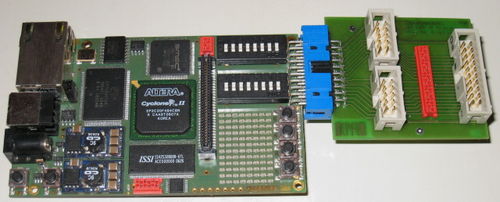
Extension for 20pins connector with Mubus connectors. This module provide an adapter for different kind of connectors used at LAP/EPFL for different interfaces.
The connection to FPGA4U is provided by the 20 pins adapter with :
- Gnd - 3.3V power supply
- An Ouput Clk that can by generated by a pll inside the FPGA (depend on the design) or I/O
- An Input Clk that can be used as input clk to the FPGA, or I/O
- 16 bits of general purpose to/from the FPGA
If the design has to be connected to the 20 pins Muibus interface a specific VHDL adapter module is needed.
From the 16 pins I/O, they are connected to 2 x 10 pins connectors with :
- Power supply Gnd - 3.3V
- 8 bits I/O
Schematic
FPGA4U Mubus Extension (.pdf)
Photo
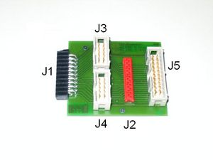
Connector pinning
|
|
Tcl file assignement
For .tcl assignment file :
# Connector J5 used for Mubus############################################
set_location_assignment PIN_U18 -to Mubus_IRQ_nset_location_assignment PIN_G7 -to Mubus_DATA[0]set_location_assignment PIN_H8 -to Mubus_DATA[1]set_location_assignment PIN_F8 -to Mubus_DATA[2]set_location_assignment PIN_H9 -to Mubus_DATA[3]set_location_assignment PIN_E9 -to Mubus_DATA[4]set_location_assignment PIN_F10 -to Mubus_DATA[5]set_location_assignment PIN_G11 -to Mubus_DATA[6]set_location_assignment PIN_E11 -to Mubus_DATA[7]set_location_assignment PIN_H7 -to Mubus_P_nset_location_assignment PIN_C7 -to Mubus_R_nWset_location_assignment PIN_G8 -to Mubus_Adr[0]set_location_assignment PIN_E8 -to Mubus_Adr[1]set_location_assignment PIN_F9 -to Mubus_Adr[2]set_location_assignment PIN_H10 -to Mubus_Adr[3]set_location_assignment PIN_H11 -to Mubus_Adr[4]set_location_assignment PIN_F11 -to Mubus_Adr[5]