Description
The MT9V032 is a camera module for the FPGA4U. The Micron MT9V032 sensor is available in Color (RGB bayer) or B/W, with a resolution of 752x480.
There exist two versions with the sensor:
Parallel board
The sensor board is directly connected to the FPGA4u.
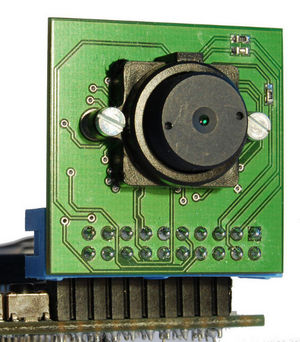
Parallel version of the MT9V032 board
If you use the version A of the board, don't forget to set to 1 the 2 switchs of the I2C, as the pull-ups were forgotten. This was corrected for the version B of the board.
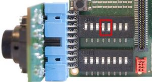
Pull-ups for the Version A of the board
Serial board
The sensor board is connected to the FPGA4U through a RJ45 cable. The image signal is sent in serial (LVDS). The board connected to the FPGA4U deserialize the signal and sent it to the FPGA4U. The pins of the serial and parallel version are the same. Only the feedback pins is different (LED_OUT for parallel version and 3.3V feedback for the serial one).
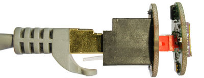
Sensor board with the RJ45 cable
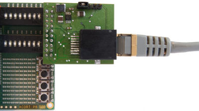
Deserializer board connected to the FPGA4U
Schematics
Parallel board
MT9V032 parallel B schematic
MT9V032 parallel B layout (to solder the components)
Serial board
MT9V032 sensor B schematic
MT9V032 sensor B layout (to solder the components)
RJ45 connector B schematic
RJ45 connector B layout (to solder the components)
FPGA4U deserializer A schematic (there is no B version)
FPGA4U deserializer A layout (to solder the components) (there is no B version)
VHDL module
The VHDL module capture the image from the camera and store it in the SDRAM. The configuration of the image sensor is done with an "external" I2C module.
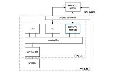
System with the MT9V032 module and the I2C to configure the camera
The internal view of the MT9V032 module
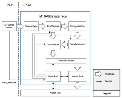
The internal view of the MT9V032 module
The sysclk must be provided with a PLL outside the MT9V032 module. The frequency supported by the sensor is between 13 and 27 MHz (30 to 60 fps).
Registers
Registers Table
| Offset |
Name |
Description
|
| 0 |
status |
Status of the controller
|
| 1 |
control |
Control the controller
|
| 2 |
startAddress1 |
First address where the images will be stored.
|
| 3 |
startAddress2 |
Second address where the images will be stored.
|
| 4 |
lastBufferAdd |
Address where the last image was stored
|
| 5 |
pixel cnt |
Number of stored pixels
|
| 6 |
colorCorrection |
correction to be applied in the image
|
|
Status register Table
| Bit(s) |
Name |
Description
|
| 0 |
B/W |
0 : For the color version of the sensor.
1 : For the black and white version of the sensor. Bypass all the color correction and management.
|
| 1 |
Video |
0 : Snapshot mode. Only one image is captured.
1 : Video mode. Images continuously stored. To stop process, use stop command (bit 2 of control register).
|
| 2 |
finished |
0 : The frame is not yet finished.
1 : The frame is finished.
|
| 3 |
running |
0 : The module is currently not running.
1 : The module is performing the acquisition.
|
| 4 |
IRQ |
0 : IRQ is disabled.
1 : IRQ are sent after each frame saved.
|
| 5 |
8 bits |
0 : 10 bits color. The pixel must use 32 bits.
1 : 8 bits color. The pixel can use either 32 or 24 bits.
|
| 6 |
BGR |
0 : The pixel are stored in the RGB order (R is on lower byte).
1 : The pixel is stored in the BGR order (B is on the lower byte).
|
| 7 |
24 bits |
0 : Will store 32 bits for each pixel.
1 : Will store only 24 bits of the pixel. Must be used with 8 bits per color!
|
| 8-9 |
ICMode |
00 : InputControl is configured for the parallel version of the PCB
01 : InputControl is configured for the serial version of the PCB. Data received is 8 bits for pixel, 1 bit for FV and 1 for LV. (default mode of the sensor in LVDS mode).
10 : not used yet. Todo. Will manage the serial version of the PCB, with 10 bits for the pixel data. FV and LV are embedded.
11 : not used
|
| 10 |
feedback |
0 : The sensor send no signal.
1a : For the serial version, 1 means the sensor is connected.
1b : For the parallel version, the LED ON signal is on. The camera is capturing an image.
|
|
Control register Table
| Bit(s) |
Name |
Description
|
| 0 |
B/W |
0 : For the color version of the sensor.
1 : For the black and white version of the sensor. Bypass all the color correction and management.
|
| 1 |
Video |
0 : Snapshot mode. Only one image is captured.
1 : Video mode. Images continuously stored. To stop process, use stop command (bit 2 of control register).
|
| 2 |
stop |
0 : Nothing.
1 : For video mode only. The video is stopped.
|
| 3 |
start |
0 : Nothing.
1 : A start command is performed. The others bits are saved for the next image captured.
|
| 4 |
IEN |
0 : No IRQ will be sent at the end of each fram.
1 : An IRQ will be sent at the end of each frame.
|
| 5 |
8 bits |
0 : 10 bits color. The pixel must use 32 bits.
1 : 8 bits color. The pixel can use either 32 or 24 bits.
|
| 6 |
BGR |
0 : The pixel are stored in the RGB order (R is on lower byte).
1 : The pixel is stored in the BGR order (B is on the lower byte).
|
| 7 |
24 bits |
0 : Will store 32 bits for each pixel.
1 : Will store only 24 bits of the pixel. Must be used with 8 bits per color!
|
| 8-9 |
ICMode |
00 : InputControl is configured for the parallel version of the PCB
01 : InputControl is configured for the serial version of the PCB. Data received is 8 bits for pixel, 1 bit for FV and 1 for LV. (default mode of the sensor in LVDS mode).
10 : not used yet. To Do. Will manage the serial version of the PCB, with 10 bits for the pixel data. FV and LV are embedded.
11 : not used
|
| 10 |
feedback |
0 : The sensor send no signal.
1a : For the serial version, 1 means the sensor is connected.
1b : For the parallel version, the LED ON signal is on. The camera is capturing an image.
|
|
Control register Table
| Offset |
Name |
Bits 31-30 |
Bits 29-20 |
Bits 19-10 |
Bits 9-0
|
| 6 |
colorCorrection |
|
factor3 |
factor2 |
factor1
|
|
Image format
The image resolution is 752x480 pixels. Each pixel can be stored in 24 or 32 bits RGB or BGR. Each color can be 8 or 10 bits. For a 10 bits resolutions, you must use 32 bits per pixel. In this case, only 30 bits will be useful bits.
The format for the 24 bits (RGB) with 8 bits resolutions:
24 bits RGB
| Bits 23-16 |
Bits 15-8 |
Bits 7-0
|
| B |
G |
R
|
|
24 bits BGR
| Bits 23-16 |
Bits 15-8 |
Bits 7-0
|
| R |
G |
B
|
|
The format 32 bits RGB and BGR with 8 bits resolution
32 bits RGB
| Bits 31-24 |
Bits 23-16 |
Bits 15-8 |
Bits 7-0
|
| |
B |
G |
R
|
|
32 bits BGR
| Bits 31-24 |
Bits 23-16 |
Bits 15-8 |
Bits 7-0
|
| |
R |
G |
B
|
|
The format 32 bits RGB and BGR with 10 bits resolution
32 bits RGB
| Bits 31-30 |
Bits 29-20 |
Bits 19-10 |
Bits 9-0
|
| |
B |
G |
R
|
|
32 bits BGR
| Bits 31-30 |
Bits 29-20 |
Bits 19-10 |
Bits 9-0
|
| |
R |
G |
B
|
|
SOPC builder
This module use the burst capability of the Avalon bus. To be able to use the burst, in SOPC builder, the arbitration value for the master part of the module must be set to 32.
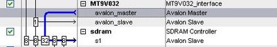
Configuration of the arbitration value in SOPC builder
C library
Some functions to control the MT9V032 controller are available. They can be downloaded with the VHDL code FPGA4U camera modules MT9V032#VHDL_and_C_code_for_the_MT9V032_module
In the following functions, int* xpCamera is a pointer to the MT9V032 module in the avalon bus.
start the acquisition of a single image
void MT9V032_startFoto(int* xpCamera,int* xpImageAddress,int options);
start the acquisition of continues images
void MT9V032_startVideo(int* xpCamera,int* xpImageAddress1,int* xpImageAddress2,int options);
configure the image sensor through the I2C to send the image via the LVDS outputs pins.
void MT9V032_configure_LVDS(int* i2c);
configure the module to correct the color with the indicated temperature.
void MT9V032_configWhiteBalance(int* xpCamera,int temperature);
the available options are the bits of the control register:
MTV_MODE_BW - indicate the camera is the B/W version
MTV_INTERRUPT - enable the interrupt when a frame is captured
MTV_MODE8Bits - 8 bits resolution for each color
MTV_MODEBGRBits - order of the pixels is BGR (instead of RGB)
MTV_ICMODEPARRALLEL - indicate the PCB connected is the parallel version (default mode)
MTV_ICMODESERIAL1 - indicate the PCB connected is the serial version
VHDL and C code for the MT9V032 module
[MT9V032.zip]
Documentation
27 MHz CRYSTAL CLOCK OSCILLATOR
Deserializer DS92LV1212A
MAX1674 step-up
I2C extender P82b715
Tps79333 200mA LOW-DROPOUT LINEAR REGULATORS
Connector pinning
Port 20 Pins Table
| 20Pin Num J1 |
FPGA Pin |
FPGA function |
Camera Pin
|
| 1 |
|
|
VCC
|
| 3 |
PIN_U18 |
Ext_Clk_In (IO/PLL4_OUTn) |
DOUT0
|
| 5 |
PIN_H8 |
SWITCH0[1] |
DOUT2
|
| 7 |
PIN_H9 |
SWITCH0[3] |
DOUT4
|
| 9 |
PIN_F10 |
SWITCH0[5] |
DOUT6
|
| 11 |
PIN_E11 |
SWITCH0[7] |
DOUT8
|
| 13 |
PIN_C7 |
SWITCH1[1] |
FV
|
| 15 |
PIN_E8 |
SWITCH1[3] |
SDATA
|
| 17 |
PIN_H10 |
SWITCH1[5] |
PIXCLK
|
| 19 |
PIN_F11 |
SWITCH1[7] |
EXPOSURE
|
|
| 20Pin Num J1 |
FPGA Pin |
FPGA function |
Camera Pin
|
| 2 |
PIN_T18 |
Ext_Clk_Out (IO/PLL4_OUTp) |
SYSCLK
|
| 4 |
PIN_G7 |
SWITCH0[0] |
DOUT1
|
| 6 |
PIN_F8 |
SWITCH0[2] |
DOUT3
|
| 8 |
PIN_E9 |
SWITCH0[4] |
DOUT5
|
| 10 |
PIN_G11 |
SWITCH0[6] |
DOUT7
|
| 12 |
PIN_H7 |
SWITCH1[0] |
DOUT9
|
| 14 |
PIN_G8 |
SWITCH1[2] |
LV
|
| 16 |
PIN_F9 |
SWITCH1[4] |
SCLK
|
| 18 |
PIN_H11 |
SWITCH1[6] |
LED_OUT
|
| 20 |
|
|
GND
|
|
Serial version
Cable 8 Pins Table
| 8Pin Num |
Cable Pin
|
| 1 |
LVDS_P
|
| 3 |
SCLK_EXT
|
| 5 |
CONNECTION_FEEDBACK
|
| 7 |
5V
|
|
| 8Pin Num |
Cable Pin
|
| 2 |
LVDS_N
|
| 4 |
SDA_EXT
|
| 6 |
EXPOSURE
|
| 8 |
GND
|
|
Conan connector
Conan 8 Pins Table
| 8Pin Num |
Cable Pin
|
| 1 |
GND
|
| 3 |
LVDS_P
|
| 5 |
5V
|
| 7 |
SCLK_EXT
|
|
| 8Pin Num |
Cable Pin
|
| 2 |
CONNECTION_FEEDBACK
|
| 4 |
LVDS_N
|
| 6 |
EXPOSURE
|
| 8 |
SDA_EXT
|
|
Tcl file assignement
For .tcl assignment file :
# MT9V032 20 pin connector
#################################################
set_location_assignment PIN_T18 -to MT9V032_sysclk
set_location_assignment PIN_H10 -to MT9V032_pixclk
set_location_assignment PIN_C7 -to MT9V032_FV
set_location_assignment PIN_G8 -to MT9V032_LV
set_location_assignment PIN_U18 -to MT9V032_pixel[0]
set_location_assignment PIN_G7 -to MT9V032_pixel[1]
set_location_assignment PIN_H8 -to MT9V032_pixel[2]
set_location_assignment PIN_F8 -to MT9V032_pixel[3]
set_location_assignment PIN_H9 -to MT9V032_pixel[4]
set_location_assignment PIN_E9 -to MT9V032_pixel[5]
set_location_assignment PIN_F10 -to MT9V032_pixel[6]
set_location_assignment PIN_G11 -to MT9V032_pixel[7]
set_location_assignment PIN_E11 -to MT9V032_pixel[8]
set_location_assignment PIN_H7 -to MT9V032_pixel[9]
set_location_assignment PIN_F9 -to MT9V032_SCL
set_location_assignment PIN_E8 -to MT9V032_SDA
set_location_assignment PIN_H11 -to MT9V032_FEEDBACK
set_location_assignment PIN_F11 -to MT9V032_EXPOSURE