FX2
From Fpga4u
The main goal of the FX2 chip is to provide an efficient replacement to the USB-Blaster cable from Altera. This cable allows connecting an USB port from a PC to the the JTAG port of a FPGA. It can be used to program the FPGA, to download object code run by a softcore processor, to debug this code or to provide a serial interface to the FPGA.
Aside from its primary goal, the FX2 can be used to provide a fast USB interface between the FPGA and a host computer. It is particularly interesting when, for instance, the video frames of a camera connected to the FPGA have to be acquired by the PC. A so-called FIFO interface is used for this purpose. The FX2 can also serve as a stand-alone microprocessor for the teaching of embedded systems.
Contents
FX2 Short Description
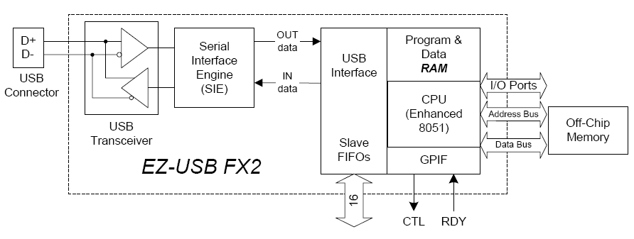
The Cypress Semiconductor EZ-USB FX2 is a single-chip solution that provides an USB 2.0 interface. It is composed of a combination of 8051-based CPU and an USB interface (see Figure below). The Serial Interface Engine (SIE) is able to perform a full USB enumeration independently of the microprocessor. This allows the software of the 8051 to be downloaded via USB. After the code is running, the chip can re-enumerate under another identity.
An optional EEPROM can be attached to the I2C lines of the microcontroller. Depending on the first byte of the EEPROM at power-up, the chip can either enumerate as a standard Cypress device, enumerate as a custom device whose characteristics follow in the EEPROM, or load a firmare from the EEPROM into the microcontroller.
To benefit from the high speed of the USB 2.0 standard, it is necessary to bypass the CPU of the FX2 when transferring data from the host. For this reason, the FX2 contains four slave FIFOs. The reading/writing of the FIFOs is done through a bus interface on the side of the device. The FIFOs transfers to/from the host are automatically performed by the FX2 using the USB interface.
For more details, we refer to the exhaustive FX2 Technical Reference Manual.
FX2 Firmware
The FX2 mainly aims at replacing the expensive USB-Blaster cable from Altera. Starting from an ingenious framework found on the Web (Kolja Waschk's usbjtag project), the FX2 firmware has been enhanced with the features that suit to our hardware platform. Shortly, the firmware firstly initializes the USB interface. USB events are then handled by specific functions.
Since the beginning of this project, several firmware versions have been implemented.
The firmware v1.0 (no longer used), which was derived from the usbjtag project, was designed under the KEIL tools (proprietary). This firmware is not compatible with the Altera's driver (version 4.0.0) provided with Quartus II 7.0 and later.
Starting from the firmware v2.1, we switched from KEIL to SDCC. This firmware includes all the functionality of the v1.0 and works with the new Altera drivers. This version allows download and debug by JTAG through USB as well as FX2 FIFO access.
Releases
- Except for v1.0, all the releases need the SDCC compiler to build. If you are developing on Windows, we suggest you to use cygwin to run the Makefile.
- The different steps to load a new firmware on the FPGA4U are detailed here.
v4.2.0 firmware (current release)
The v4.2.0 firmware fixes a bug that occurred on OSX or Linux based systems while programming the board in High-speed. With this fix, it is no more necessary to force the Full-speed mode before programming the board.
- The sources of this firmware.
v4.1.0 firmware
The v4.1.0 firmware provides a vendor command (0x94) to get the version number. Here's an example program to get the version(you'll need to have read and write access to the device, usually located in /dev/bus/usb/<bus_number>/<device_address>, you can find the bus number and device address in the output of the "lsusb" command, the device name is "Altera"):
#include <stdio.h>
#include <stdlib.h>
#include <libusb-1.0/libusb.h>

#define TIMEOUT 2000 // in milliseconds

// Hopefully the version string length won't overflow this
#define BUFSIZE 200

#define VERSION_REQUEST 0x94

int main(int argc, char *argv[]) {
    if (argc < 3) {
        fprintf(stderr, "Usage: %s <bus_number> <device_address>\n", argv[0]);
        return 1;
    }
    libusb_init(0);
    libusb_device **list;
    libusb_device *fpga = 0;
    int n = libusb_get_device_list(0, &list);
    printf("%d usb devices available\n", n);
    int i;
    for (i = 0; i < n; i++) {
        libusb_device *device = list[i];
        if (libusb_get_bus_number(device) == atoi(argv[1]) && libusb_get_device_address(device) == atoi(argv[2])) {
            fpga = device;
            break;
        }
    }
    if (i == n) {
        fprintf(stderr, "Error: no usb device with specified bus number and device address accessible\n");
        return 1;
    }
    libusb_device_handle *dh = 0;
    int err = libusb_open(fpga, &dh);
    if (err != 0) {
        fprintf(stderr, "Error opening device: %d\n", err);
        return 1;
    }
    char version[BUFSIZE];
    for (i = 0; i < BUFSIZE; i++) {
        version[i] = '\0';
    }
    int ret = libusb_control_transfer(dh, LIBUSB_REQUEST_TYPE_VENDOR | LIBUSB_ENDPOINT_IN, VERSION_REQUEST, 0, 0, version, BUFSIZE, TIMEOUT);
    if (ret < 0) {
        fprintf(stderr, "Error asking for version info: %d\n", ret);
        return 1;
    }

    printf("Firmware version reported: ");
    for (i = 0; i != 200 && version[i] != '\0'; i++) {
        printf("%c", version[i]);
    }
    printf("\n");
    libusb_free_device_list(list, 0);
    return 0;
}
Build with gcc -o ver ver.c -lusb-1.0
Due to many compatibility issues with system designed for firmware v1, the FIFOs for bulk transfers are now configured to be synchronous, by default. It is still possible to switch between the synchronous and asynchronous mode with a vendor command (0x93), as illustrated in this small example:
char data[2];
int rv = usb_control_msg(device,
                     USB_TYPE_VENDOR | USB_ENDPOINT_IN,
                     0x93,  // The vendor command
                     0,     // value
                     0,     // index (0 for synchronous and 1 for asynchronous)
                     data,  // returned data
                     2,     // size of data
                     2000); // timeout in ms
if(rv<0)
  printf("Error while trying to switch to sync mode: %s\n", usb_strerror());
else
  printf("Switching to sync mode (should return 'index'): %d\n", data[0]);
- You can retrieve the source of this version in the history of the firmware.
v2.1 firmware files
This firmware is compatible with the new Altera USB drivers. It has exactly the same functionality as the v1.0 firmware, except for the FIFOs buffer, which are configured in asynchronous mode.
v2.1 firmware with SPI master
This is a version of the v2.1 firmware that integrates a SPI master. More details can be found here.
v1.0 firmware files (KEIL tool)
This firmware can only be used with the Quartus versions under 6.0. However if you still want to use it, you can download it here.
For more details about this code, we refer to the comments in the source files and to the following file FX2_USB_Blaster.pdf.
Detailed Description
System mode
By default (through our configuration of the IFCFG register), the FX2 is in slave FIFO mode. Thus, to read and write data from the EP6 and EP8, the FPGA will have to assert the correct signals on the FX2 (Trm chapter 9). The FX2 clock is 48Mhz and can be used on the FPGA through the IFCLK pin of the FX2. However, asynchronous mode is enabled by default but can be changed using the USB vendor command 0x93.
USB speed
The FX2 is set to high-speed USB (480 Mb/s) by default. It seems that the USB-Blaster emulation does not work properly on Linux in this mode. For this reason, it is possible to change it to full-speed (12 Mb/s) with the USB vendor command 0x91 which will set the second bit of the CT1 register in the FX2.
Power consumption and enumeration
In the enumeration process, the devices cannot draw more than 100 mA. Therefore, the FPGA has to be disabled, as it is a major power consumer (especially with all the LEDs on). This is done by stopping the 1.2V converter (put a high level on PE6, necessary for the FPGA) until the host has recognized the chip as a USB device.
When an external power is connected to the FPGA4U board, there is no need to ask the host for supplementary power.
If a design is on the FPGA external flash memory and the power supplied by an external power, the FPGA is powered.
JTAG port
On the FPGA4U board, the JTAG port of the FPGA is accessible by the FX2 chip or by an external connector (usually not soldered). To avoid shortcuts, the FX2 has to enable drivers before using the JTAG port. The JTAG is enabled by default. To dynamically change this setting, the vendor command 0x92 is used (switch via PC7).
FIFOs and endpoints
The next picture shows the USB device information provided by our V2.1 firmware.
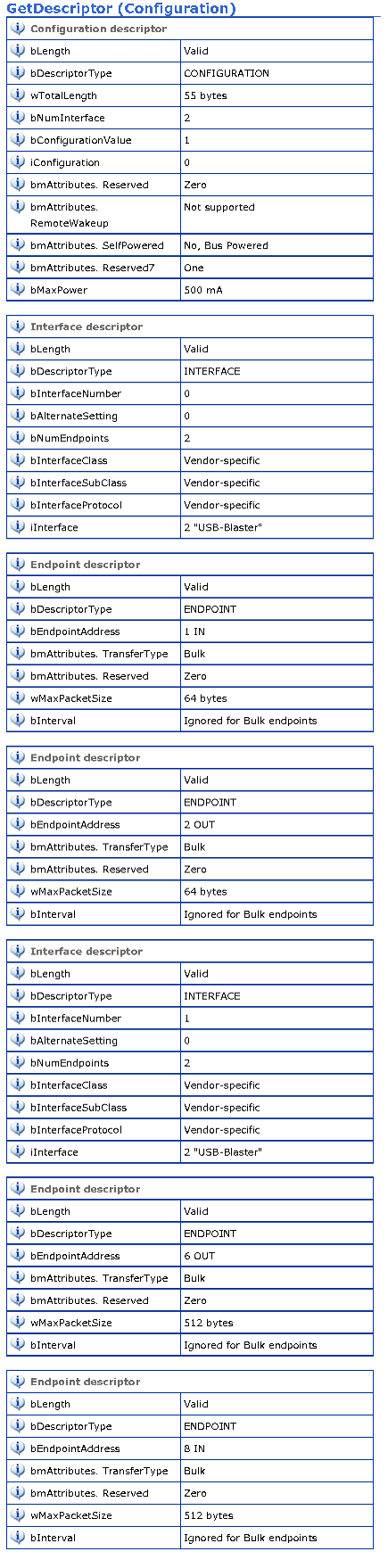
As showed in the descriptors returned to the PC during the enumeration process, 4 endpoints are used:
- Endpoints 1 IN and 2 OUT (EP1 single buffered, EP2 double buffered) are used by the JTAG part of our emulated USB Blaster, to program the FPGA, download the object code to the softcore processor
- Endpoints 6 OUT and 8 IN (EP6 and EP8 double buffered) are used for user communication, in order for the computer to communicate directly with the FPGA
Data sent to/from the endpoints 1 and 2 are directly stored in the FX2 buffers where they will be processed by the JTAG part of the firmware. Endpoints 6 and 8 use the FX2 FIFOs in order to do the communication between the host computer and the FPGA.
Two interfaces are used in order to be compatible with the Altera driver.
The maximum packet size for the endpoints 6 and 8 are 512 bytes when the FPGA4U is connected in high speed and 64 bytes when connected in full speed.
Firmware tools
If you are developing new firmwares or just want to play with other firmwares, these pointers can be useful.
- Check out Cypress website for the device (FX2 LP 68013A) developer kit.
- To load a firmware you can use our Migration Tool. Its usage is described here.
- You can also use the tools provided by Cypress to upload a firmware onto the FX2. For that, follow these steps:
- Remove the jumper near Ethernet connector
- Connect FPGA4U.
- Run EZ-USB control panel
- Place the jumper again
- Click on EEPROM button
- Select the .HEX file to program
- That's all
- Unconnect and connect the board again, it has to work
- You can also use fxload on linux or the following port of fxload for windows.
Firmware details (for developers)
Here are detailed the different important functions added between the usbjtag projet and our firmware version, due to our specific design and the additional communication endpoints.
During the initialisation (not exhaustive):
- IOE = (1 << 6);: the 1.2V converter is disconnected, as we can not draw more than 100mA during the enumeration process, will be connected once enumerated
- IFCONFIG = bmIFCLKSRC | bm3048MHZ | bmIFCLKOE | bmIFCFG1 | bmIFCFG0;: here we set the system in FIFO mode by default, as we use EP6 and EP8 as communication endpoints between the FPGA and our computer
- REVCTL = 3; SYNCDELAY;: allow firmware access to fifo buffers, disable endpoint auto arming, synchronisation delay is needed after such an operation
- FIFORESET = 0x80; SYNCDELAY;: NAK all incoming packets and requests
- FIFORESET = 0xXX; SYNCDELAY;: reset each FIFO
- FIFORESET = 0x00; SYNCDELAY;: restore normal behaviour
- EPXFIFOCFG = XXXX; SYNCDELAY;: configure fifo mode for each endpoint
- EPXCFG = XXXX; SYNCDELAY;: configure endpoint settings
- REVCTL = 0; SYNCDELAY;: enable endpoint auto-arming (packets automatically acknowledged & transfered) when the CPU sees a transition of an AUTOIN/AUTOOUT bit (used for the EP6 and 8 where FIFOs are used to transfer packets )
- EP6FIFOCFG = bmAUTOOUT | bmWORDWIDE; SYNCDELAY;: EP6 OUT, data is automatically committed, FX2 is interfaced to the FPGA via a 16bits bus, endpoint will be automatically re-armed because of the transition on the AUTOOUT bit
- EP8AUTOINLENH/L = XXXX; SYNCDELAY;: for EP8 IN, define in byte the size of the IN data automatically commited
- EPXBCL = 0x80; SYNCDELAY; * 2 : arm EP X OUT by writing byte count w/skip
While the system is working:
OUT packets are automatically committed to the FX2 FIFOs, thus the FPGA needs to assert the correct signals in order to recover the data (see the technical reference manual).
To send a packet which size is not the maximum packet size, the FPGA can use the PKTEND line.
FLAGB and FLAGC pins show respectively the full and empty status of the currently selected fifo.
libusb-win32
To communicate with the board, the libusb package can be very helpful. If you run windows, you can get it at http://libusb-win32.sourceforge.net/ For linux systems, you can find it here: http://www.libusb.org/
A summary of the documentation for programmers : libusb Developers Guide (version 0.1) from http://libusb.sourceforge.net/doc/ is the documentation for the 0.1 version.
Libusb 1.0 is in active development (http://libusb.sourceforge.net/api-1.0/index.html), and for now is only available for linux.