Create a block diagram
From Fpga4u
The block diagram is used to draw logical circuits with predefined components. To create one, draw manually the circuit of the multiplier and follow the instructions:
- Select File-->New
- Choose Block Diagram/Schematic File
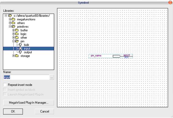
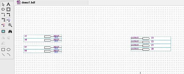
- Now you have a workspace on which you can compose your cicuit: double-click on the grid and choose the components you want to add. The logical gates are stored in primitives->logic. Note: using CTRL and the mouse allows you to copy the selected component.
- Save and compile your work (use the Start Compilation icon or select Processing->Start Compilation), correct potential errors.
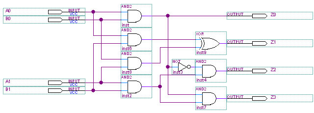
Here is an example of design for the 2 bits multiplier:
Links
http://www.altera.com/literature/quartus2/lit-qts-synthesis.jsp - For more information on the Quartus II synthesis tool


